
VIS Hydraulics IRA0.M27



Product specifications
| Product Attributes | Test method | ||
|---|---|---|---|
| Weight (Kg) | 0.14 | ||
| Installation torque (Nm) | 70 To 80 | ||
| Filtration | 20/18/15 ISO 4406 (maximum filtration admitted) | ||
| Orientation | Norestrictions | ||
| Oil Testing Conditions | ISOVG46cSt | ||
| Fluid | Mineral | ||
| Pressure Attributes | Test method | ||
|---|---|---|---|
| Max Pressure (Bar) | 400 | ||
| Flow Attributes | Test method | ||
|---|---|---|---|
| Max Flow (l/min) | 150 | ||
| Viscosities (cSt) | 7.4 To 420 | ||
Product Description
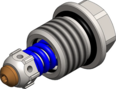
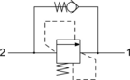
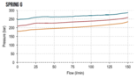
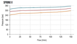
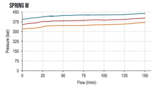
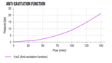
The IRA valve combines in one compact insert cartridge the typical function of shock relief valve and anticavitation through thecheck valve. In the pressure relief function it’s a side-in nose-exhaust valve, with very low pressure rise thanks to the smart deflectordesign. When the pressure at the high pressure inlet (2) reaches the valve setting, the valve starts to open to tank (1). In the freereverse flow function a very light bias spring allows for ease of flow passage from nose to side (1 to 2). High precision machiningguarantees quick response to load changes, limited hysteresis and reduced internal and external leakage.
Related Documentation
For more information, download the documents below
Request the 3D drawing
Working this component into your own design? Request the STEP file and we'll send it straight to your inbox


